NKU-M specification made with the usage of standard modules allows:
- to create an effective configuration of cases with necessary number of constructive elements depending on rated current of a feeder device and functional purpose,
- to facilitate making changes while realizing the project due to interchangeability of functional blocks,
- to replace modules and complement installations without killing collecting buses and adjacent connections of the board immediately,
- to reduce to maximum expenses for its modernization without strict time restrictions and without expenses on reserve equipment, without worsening the operational integrity,
- to provide compatibility of the equipment of different manufacturers within the limits of one project that results in optimization of the system cost, especially in comparison with its import analogues.
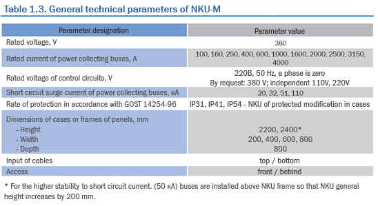
NKU-M general technical parameters are shown in table 1.3.
Operating conditions
- Height above sea level 1000м
- Operation temperature from minus 25 up to plus 50°С
- Type of atmosphere according to GOST15150-69 - II

Design and notation of modules
NKU-M cases are installed in specialized premises and are the devices of double-sided service. The unified system of frame structures and collecting buses allows to make boards both with back, and front connection, providing thus an optimum access level for servicing the equipment.
Installation of NKU-M cases in electric premises is possible both in one row, and in two ones. In the case of two-row installation the cases buses located in different rows are connected with a bus bar bridge, which is delivered under the order with NKU-M. At double-sided service of cases the distance between a case and a wall must not be less than 800 mm.
Frame structures of NKU-M case are the basis for MCC installation. The system of holes and grooves in a frame allows, without additional machining, to divide elements into sections and to install necessary functional devices and buses. Frame structures are placed on a socle.
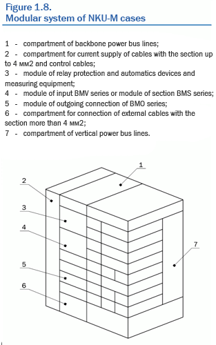
Each NKU-M case consists of compartments (see figure 1.8), which being collected in different combinations and numbers allow to make any MCC configurations.
According to their purpose, NKU-M case compartments are subdivided into:
- compartments for installation of functional equipment (input modules of BMW series, section modules of BMS series, modules of outgoing connections of BMO series);
- compartments for installation of auxiliary devices (links, counters, current transformers; devices of relay protection and automatics);
- compartments for installation of collecting buses;
- compartments for connections of cables.
The cases design provides three types of installation of devices depending on the type and functional purpose of the module:
- on sliding chassis for installation of automatic switches;
- on sliding modules for installation of devices set (automatic switch, starting box, etc.);
- stationary blocks of relay protection and automatics, measuring equipment.
Modules for outgoing connections supply are sliding systems of two standard sizes: for rated current up to 25A and up to 80А. They are characterized by a high degree of operating reliability and provide necessary safety of maintenance staff. The devices inside the block is installed on special planes and holders, thus their composition allows making service of the block in its test position.

The applied system of modules movement with slideways allows using heavy equipment, and the absence of rotating mechanisms makes the system of movement extremely simple and reliable.
For connecting modules to power bus lines and for secondary control circuits supply releasable connections with plugs installed on the back wall of the module, sockets - on the mounting panel, being at the same time a protecting schield, closing a compartment of vertical buses, are used.
For exact and reliable conjunction of plug-in points of contact auxiliary pins are applied, which are installed on the back wall of the module.
Sliding modules can be in three possible positions:
- the module is in working position slid shut into NKU-M, the main circuits and control circuits are closed;
- the module is slid shut into NKU-M, the main circuits are open, control circuits are closed;
- the module is not slid shut into NKU-M, the main circuits and control circuits are open.
In cases sliding modules are supplied with locks, preventing:
- a sliding element being slid shut into, with the automatic switch turned on;
- drawing out a sliding element of the attached position into the test one, with the automatic switch turned on;
- turning on the automatic switch installed on a sliding element in intermediate positions (not fixed in attached and test positions).
The design of the modules provides using two kinds of automatic switches drivers:
- the manual drive going through a door (a remote handle);
- the electric remote drive.

Protection equipment
In modules of BMV, BMS series there can be installed:
- automatic switches of Compact NS series of MERLIN GERIN,
- automatic switches of DPX series of Legrand,
- automatic switches of BD series of OEZ;
- automatic switches of NZM series of Moeller.
In modules of BMV, BMS series the following types of protection are provided:
- protection against overloads with adjustable setting Ir;
- protection against short circuit with adjustable setting Im with a constant time setting;
- current cutoff with a constant setting.
Installation of other types of electronic releases with a big set of protection (by request) is possible.
When NKU-M is supplied from two-transformer substation, application of ASA is possible with electromechanical relays or microprocessor blocks.

Protection equipment
In modules of BMO series there can be installed:
- automatic switches of Multi 9 series of MERLIN GERIN,
- differential switch of Vigi С60 series of MERLIN GERIN,
- automatic switches of GV2, GV3 series of Telеmecanique,
- the relay of Telemecanique,
- contactor switches of LC1, LC2, LR1 series of Telеmecanique,
- automatic switches of LR, DX, RCBO series of Legrand,
- automatic switches of PKZ series of Moeller,
- contactor switches of Dilm series of Moeller.
In modules of BMO series the following kinds of protection are provided:
- protection of the main circuit against short circuit,
- protection of the main circuit against overload,
- protection of the main circuit against leakage currents on the ground,
- protection of control circuit against short circuit.
Collecting buses include the main and vertical distribution buses located in completely closed compartments. The backbone buses are located at the top of a case and are connected when linking cases by means of cover plates fastened by bolts. Vertical buses are located behind devices compartment. Connection of the backbone and vertical buses can be done both with the help of bolted connection, and welding.
Backbone buses serve for electric power distribution to the cases making up a distribution board. Vertical buses serve for electric power distribution to various case branches.
The compartment of cables connections of the section up to 4 мм2 and of control cables is a cell adjoining to devices compartment. Its location depends on a type of service.
In the compartment for cables connections of the section more than 4 мм2 there are power links on special brackets. Power cables pass from the electric raceway and are directly connected to links.
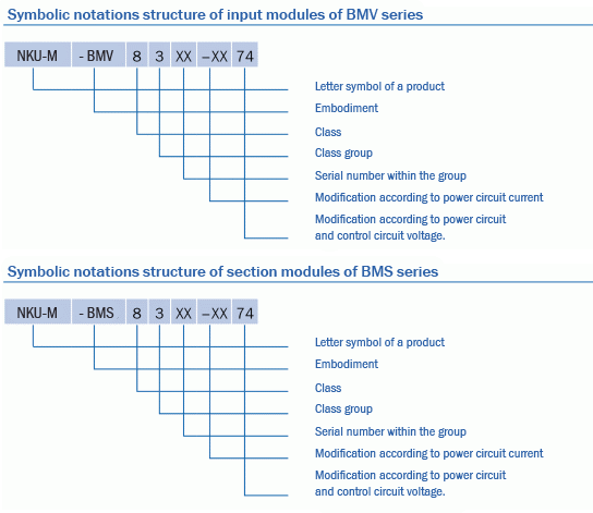
| БМХ | | 8 | | 3 | | Х | | Х | | Х | | УХЛ4 | | |
|
| | | | | | | | | | | | | | | | | | | | | | | | | | | | Обозначение функционального блока:
БМВ - блок модульный ввода
БМС - блок модульный секционирования
БМА - блок модульный аварийного ввода
|
| | | | | | | | | | | | | | | | | | | | | | | | | | | | |
| | | | | | | | | | | | | | | | | | | | | | | | | | | | Класс
8 - блок ввода и распределения электроэнергии
|
| | | | | | | | | | | | | | | | | | | | | | | | | | | | |
| | | | | | | | | | | | | | | | | | | | | | | | | | | | Группа класса
3 - блок ввода и распределения переменного тока с АВР
|
| | | | | | | | | | | | | | | | | | | | | | | | | | | | |
| | | | | | | | | | | | | | | | | | | | | | | | | | | | Порядковый номер в пределах одной группы
|
| | | | | | | | | | | | | | | | | | | | | | | | | | | | |
| | | | | | | | | | | | | | | | | | | | | | | | | | | | Модификация по току силовой цепи
|
| | | | | | | | | | | | | | | | | | | | | | | | | | | | |
| | | | | | | | | | | | | | | | | | | | | | | | | | | | Модификация по напряжению силовой цепи и цепи управления
|
| | | | | | | | | | | | | | | | | | | | | | | | | | | | |
| | | | | | | | | | | | | | | | | | | | | | | | | | | | Климатическое исполнение и категория размещения
|
| | | | | | | | | | | | | | | | | | | | | | | | | | | | |
 Non-standard electric equipment up to
  Standard electric equipment up to 1000 V
 Electric equipment above 1000 V
 Electrochemical protection
 Block-module constructions
 Metal working and services


