and high-voltage electric equipment
10 Chelyabinskaya Str., Ozersk, Chelyabinsk region, 456783, Russia
Phone: (35130) 4-36-40; fax: (35130) 4-87-15; e-mail: enerprom@aopoes.ru
Sales department. Phone: (35130) 4-82-45, 4-17-79; fax: (35130) 4-46-83; e-mail: marketing@aopoes.ru
 Non-standard electric equipment up to
  Standard electric equipment up to 1000 V
 Electric equipment above 1000 V
Complete distribution devices KRU-APS(E) of the voltage 6 and 10 kV
Complete transformer substations of KTPK-E type with the capacity from 25 up to 630 kVА and voltage up to 10 kV
Front side access switchgears of KSO-203 series
Complete switchgears of K-01E series
Complete switchgears of K-01ES series
Indoor transformer substations of KTPV series of capacity from 250 up to 1000 kVА and voltage up to 10 kV
The station of commercial account of 10 (6) kV (SCA)
 Electrochemical protection
 Block-module constructions
 Metal working and services
|
Indoor transformer substations of KTPV series of capacity from 250 up to 1000 kVА and voltage up to 10 kV
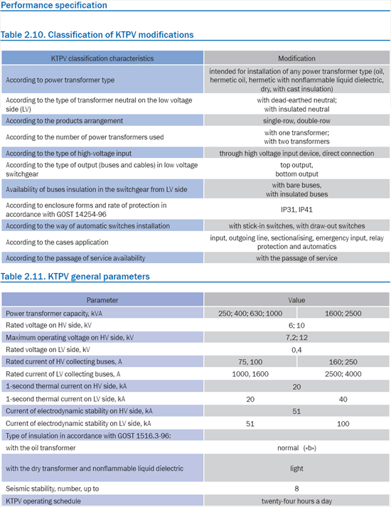
The device meets the requirements of Technical Conditions 3412-043-32574607-2005. KTPV performance specification is given in table 2.10, KTPV critical parameters are given in table 2.11.
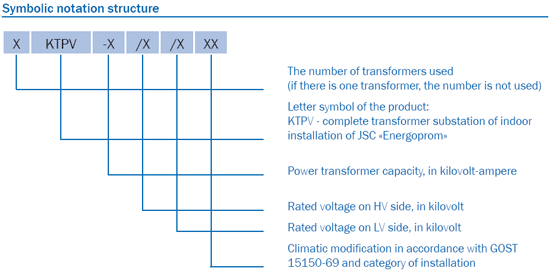
The example of symbolic notation of a two-transformer KTPV substation of capacity 630 kVА of rated voltage on HV side – 6kV, of rated voltage on LV side - 0,4 kV, a type of climatic modification U3: 2KTPV-630/6/0,4 U3 Operation conditionsRegarding influence of environmental climatic factors, KTPV corresponds to climatic modification U, category of installation 3 in accordance with GOST 15150-69 and GOST 15543.1-89 (temperature from minus 25 up to plus 50°С). Environment is not explosive, not containing current-conducting dust, aggressive gases in the concentration destroying metals and insulation. Type of atmosphere - II according to GOST 15150-69. Regarding influence of mechanical factors, it corresponds to group of operation conditions M6 in accordance with GOST 17515-72. DesignStructurally KTPV consists of:
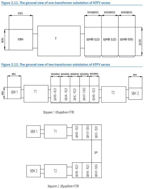
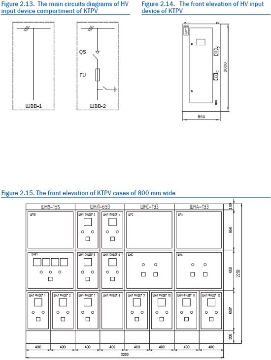
The general view of KTPV is shown in figures 2.12, 2.13, 2.14. High voltage input device represents a metal enclosure of closed modification in which, depending on the circuit, load-break switch of VNA-6 (10) U2 type with fuses of PKT‑6 (10) U3 type or any other load-break switch with similar characteristics can be installed . For maintenance personnel safe work, power bus lines going from the high voltage input device to the power transformer are placed in a box, fixed to the high voltage input device lateral wall. For localization of the arc caused by short circuit in the high voltage input device, in the roof of the device a window, in which a voltage release valve is fixed to bending loops, is provided.
With dead connection of the transformer power cables are laid in the protective box (by special request). The box design is determined by the transformer type.
As power switches in KTPV the following devices of move-out and stick-in modifications can be used:
On the doors of power compartment cases control, indication and measuring devices are installed. In busbar compartment there is power transformer input, collecting buses, branches for cable and bus bar connections, current transformers, power assemblies for outgoing cables connection. Backbone buses are fixed with cleats. In KTPV the electric and mechanical interlocks providing the maintenance personnel safe work are made. In the high voltage input device of KTPV the following interlocks are provided:
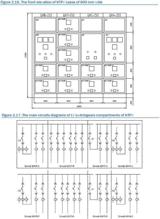
The main circuits diagrams of the high voltage input device and low voltage switchgears are shown in figures 2.16, 2.17. In two-transformer substations ASA circuit can be made both with the use of electromechanical relays, and with the use of Zelio microcontroller of "Schneider Electric", microprocessor blocks of BMRZ-0,4VV and BMPA series of JSC "Mekhanotronika". The account of active and reactive electric energy is realized by counters of any manufacturer. Account boards can be fixed to the low voltage switchgear lateral walls or the wall of KTPV premises. The advantages of KTPV of JSC "Energoprom" are the following:
Смотрите также > Блок-боксы типа 2БКТП-Э с КТПВ и НКУ |
|
skilled consultants will help you to find optimal
decision for your business!
Phone: (35130) 4-36-40; fax: (35130) 4-87-15,
e-mail: enerprom@aopoes.ru, site: www.energoprom.biz, www.enprom.ru.


